Straight lamp

I made a fully turned lamp using steel and cherry wood as a Christmas present for my sister and brother-in-law. I got the cherry wood as 2 sections of trunk about 4 years ago from my tree-surgeon house-mate. He cut them down from a tree on Colebrook Row in Islington, London. After letting them season as planks for 3 years, this is the first time I’ve used any of them.

For the design I wanted a tall thin lamp and to use a large round bulb. To make it sturdy  and resistant to being knocked over, the base is solid steel and weighs a number of kilos, but the stem and connector cup are both hollow with thin wall sections. It is made from 3 sections that screw together with the cord going up through the middle. I designed the bottom of the base to have a cover plate that can be used to mount the lamp on any wall or ceiling. The stem has a steel pipe as the core inside the cherry, so it is very rigid. The bulb holder had an earth connection and all the metal parts are touching one another, so the whole lamp is earthed as well, so I guess it would pass a PAT test.

It was fun to make it and I would be up for making more, but it does takes a real long time to finish them.

Vaudeville halloween

Me and my friends Jowan Sebastian, Tom Brimson and Liam Dennis wanted to organise a night that could double as a showcase for fun interactive things that we wanted to make. Halloween seemed like a good night for that.

With the help of Jack Williams, we put on the night at 5 below. My addition was to help create some sound effects buttons that were placed around the bar and fed through the main PA and help create a big LED filled crucifix.

The sound effects were made using a board based on Lady Ada’s Waveshield, similar to the board I made for my Mario Lamp. It consists of an Arduino shield that reads WAV files off an SD card and plays them out through a 3.5mm jack. There are 6 buttons that trigger 6 different sound effects. I made it using SMD components so I had to rejiggle the original design around a little in Eagle. Here is the board and the schematic.

This is the audio player, housed within a wooden box. 3 of the 6 buttons are mounted in the lid, for the DJ to operate.

The remaining 3 were placed inside dolls and attached around the bar.

As well as the sound box, we constructed the cross. We made MDF boxes to house the lights and covered them with tracing paper and perspex to diffuse the light.

Here is the crucifix assembled in the bar with an automatic RGB sequence.

As every halloween party needs, A spooky rupert the bear poster.

Is Land floating island

This is some info on the creation of this island project. More info on the project itself can be found at www.is-land.co.uk

For the summer festivals, me and my friend Sarah Cockings wanted to make an art piece to take along with us. The idea of Is Land, a floating island sculpture was born. We submitted a proposal to Burning Man festival in the USA and to Secret Garden Party, here in the UK, and managed to get some funding money to make our idea become a reality. We wanted to create a sculpture that was somehow seen to be floating up in the sky, yet at the same time looked as realistic as possible. We toyed with various ideas including making a sort of polystyrene/paper mache sculpture that perches on top of a pole, as well as an air inflated structure. In the end we decided that a helium filled ballon with decoration on the outside would be the best and would have the least visual connection to the surrounding ground.

We got the balloon made by Cameron balloons. We opted for a shape that looked vaguely plant-like but that still retained strength to attach decorations to and that didn’t make the cost spiral out of control.

Above is an image of the panel shapes that were stitched together to create the full size balloon. These panels were all digitally printed with images of plant foliage. below is an image of a photo of a bush that was used for the panels, along with the panel shaped photos.

Once the balloon had been made, we were ready to decorate it in preparation for Secret Garden Party. The main issue with the decoration was the weight. The balloon was roughly 47m3. As a rule of thumb, helium can lift 1kg per m3, and our balloon material and tethering weight about 19kg. This gave us 28kg to potentially play around with, but it is advisable to have at between 1/3 and 1/2 of the total lift of the volum of helium still lifting the balloon, so as to keep it pulling upwards even when there are strong gusts of wind. This left us with about 13kgs for decorating, including the decorating material, the paint and the glue.

As we were pushed for time, we decided to use copper pipe insulation cladding, which we shredded, painted and adhered to the surface of the balloon. This was designed to look like long grasses and it was hoped it would wave around gently in the wind. We did all this work in The Goods Shed in Stroud. I’d highly recommend it. Contact Neil Walker at Stroud Valley Arts (SVA)

We bought 200 2m lengths from local building supplies. This meant clearing out 3 suppliers. We then cut them into halves and thirds and started to shred them, so they had a sort of dracaena or yukka look to them.

They were painted greens and some shades of brown. To help the contact adhesive soak into the foam, a patch was cut from the surface of the foam, where there seemed to be a non-porous layer. Some of the areas were on the side of the foam tube, and some were glued end-on. For these, another section of tube was attached to provide more support to anchor to the balloon.

As well as using these painted foam fronds, we attached some pieces of plastic foliage that you can buy for decoration. These looked really good, but unfortunately were relatively a lot more expensive and normally had a metal wire core so weighed too much to use in large numbers.

We decorated the 2 bushes and some of the tree mainly with the artificial foliage.

After collapsing it down and squashing it into a transit van, we got it to the festival site and started filling it with helium.

Once it was filled with helium, we had to squeeze it underneath a powerline and above some water. Cue monkey and canoe antics.

We did manage to get it up OK. We had it tethered to the banks of the pond using Nylon rope at 4 points. We used 1m lengths of rebar bent in half, and hammered into the bank.

For a couple of days, everything went perfectly, and the sculpture was enjoyed by everyone, then….. disaster! On Saturday night/Sunday morning, some vandals managed to cut the rope tethers, allowing the balloon to float away into the atmosphere. At the time this was a major nightmare, but in time it turned out to be a bit of a blessing. The story got picked up by a load of national newspapers including The Times, The Guardian, The Observer and The Telegraph. Thanks to this exposure, we managed to get some funding from Secret Garden Party to remake the sculpture in time for Burning Man festival.

We flew out to LA, where we stayed for a week or so to try and organise everything for burning man. Because we were on regular tourist visas, we had the balloon shipped out seperately to try and avoid any customs complications. We completely failed at this aim. We spent 3 days non stop driving accross LA between various shipping company offices and the airport to get our packaged out of customs, where it was being held on a technicality, while trying to deal with the time difference with the UK. All this because the package had been sent with the wrong information from the UK. If I have any advice, it would be make sure you speak on the phone to the shipping agents at both the sending and recieving to make sure everything is understood by everyone.

Once we had the balloon, we had to find a space to use to decorate it and we found the Big Arts Lab in downtown LA. I’d highly recommend this space if anyone is in LA.

We got into the space to start decorating it. We found an improvised way to inflate it with 47m3 of air using a fan and rolled up funnel.

After a couple of days using the same technique as before, we had it finished and ready for the desert!

We had to completely provide ourselves with lighting. We rigged up 4 floodlights, running off a single generator. To wire them together, we got some trenches dug using this rad machine, the ditch witch.

For tethering, this time round, we went for stainless steel wire rope, held in place using rebar that was hammered into the desert. We had a handy mechanical friend that made it quite quick.

Once it was all set up, it was ready to inflate. We used a much better inflation system this time, with the proper piping. It took about 10 minutes to inflate with 6 cannisters this time round, instead of about 1:30hr at Secret Garden Party. Big thankyou to Airship Victoria for the tips and equipment they lent us.

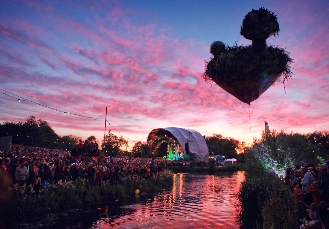
In the daytime, once it was up, it looked really nice, especially with the backdrop of the vast expanse.

After having it tethered on a 5m line to start with, we decided we wanted it up further and extended it to 25m. This worked well and meant it could be seen from all corners of the festival.

Is Land was quite a roller coaster ride of a project, with some amazing experiences along the way. There’s also the possibility of some future events with it too, that I will post about here. Feel free to contact me if you want any more information.

Embossing stamps

I was asked by Robin Mackay and Paul Chaney, who work in the workshop next door to me, whether I would be able to produce a set of embossing stamps for an upcoming issue of Robin’s philsophical journal, Collapse. I had never done this before, but I’m pretty interested in printing techniques, so jumped  at the opportunity. This next post kind of catalogues the stages I went through if anyone is interested in doing the same.

Robin wanted a sheet, almost A6 (100mm X 170mm), that contained the text of a recipe. Before I went about cutting this out, I wanted to do some smaller size experiemnts. I had heard that nylon is the best material for making the stamps, so using the little CNC mill, I cut out a male and female block from some blue Nylon we had. To start with I made the cut paths in Illustrator by outlining the text I had, then offsetting the outlined path. When making the female block, the offset needs to be inside the text to account for the angle of the engraving bit.

The engraving bit I was using was 30 degrees from vertical, which meant that if I wanted to engrave 0.2mm deep, I had to offset by (0.2 * tan30)=0.115mm. I repeated this offset until the middle of the thickest part of the text was reached. Once this was done, the text needs to be flipped for the female.

Here you can see it once it was milled out. I found that Nylon was less than ideal because of the amount of swarf that gets left attached to the block.

Here’s the male piece, where the cut path has been offset around the outside of the text.

Here you can see the results of the first stamp test. The final piece was to be on this thick matt black paper as it was part of the artwork.

I then decided to use Acetal rather than Nylon, which macines a whole lot better. I made this test block, with varying engraving depths.

Here the results using the different depths. As you can see, the shallowest engraving produced the most detailed emboss.

To achieve this fine a detail, I had to trace over each letter in the font to create a special variation for engraving. Because if you just offset the path, where there are really thin bits of the letter, the path just dissappears. To get around this, I traced a line along the centre of each letter. Evil Mad Scientist made an Inkscape extension for doing this with a tutorial on how to use it here. I use Illustrator so I did it manually, which took a while, but I prefer most of the features that are with Illustrator.

This shows the outline of the font itself.

Here you can see the actual cut paths, created by ofsetting the outline.

The plate sizes needed were slightly larger than the maximum size of the bed which is 152.3mm X 101.6mm, so I had to construct some jigs that I thought would hold both the male and female plates in the same position.

Unfortunately I was unable to get the surface of the plate flat enough to get an even engraving. In the photo above, the upper right corner is engraved OK, but the bottom end hasn’t engraved at all.

I thought I’d be able to get round the problem by machining a male and a female that were slightly smaller, to fit onto the machine bed so I could fully flatten them on the machine before cutting, and I managed to make to plates well enough, but the finished sheet had lines accros it that weren’t wanted.

On this example, you can see that the press wasn’t even from left to right. Also you can see offset lines around the text, towards the top on the left, that is from imperfect cutting of the male piece of the stamp. On top of this, the stamps don’t fully reach the top and bottom of the paper, which had all been guillotined to that size.

In the end it worked out OK. The reason that the original stamps weren’t flat on the cutting surface is because there was a jig in place so that both male and female plates were aligned, but this jig was pretty precarious. I realised that if I didn’t use the male stamp, I could just cut the female part flat on the macine bed. The press has enough pressure to flatten all the paper apart from the recesses engraved into it.

This had the added benefit of making the text easier to read because the flattened part of the paper took on a much smoother, almost glossy surface, but the raised text was left with it’s original matt finish. This made the contrast much higher.

The text of the emboss is for a recipe for a pretty gluttonous cake that is a artist commision for the Collapse journal.

Here is a picture of the press. It consists of 2 thick aluminium rollers, with the top free-rolling roller being height adjustable, and the bottom roller being connected to the handle. It is very beefy and sturdy and could easily handle the high pressures needed for the embossing.

I thought it might be nice to use this press to emboss some business cards.  engraved a little block with a nice geodesic sphere pattern.

I used the same black card used for the recipe, but when I ran them through the press, I spray glued an inkjet printed piece of white card that contained the details on. So the front of the card is a normal white business card and the back is this nice embossed geodesic pattern.

Here you can see both sides of the card. Big thanks to Alan Clarke for helping with the graphics and also for the photo.


So if anyone has an interest in trying to emboss their designs, I hope this might help. Using the female only stamp method is good in that it is simpler to create the stamp and improves the contrast between the embossed part and the pressed part, but if you want to keep a consistent texture of the paper, you’ll need to have a male part.

I’d highly reccomend using a roller press like the one above, because it makes it quick and consistent. I did try some presses using a bench vice and G-clamps but it took much longer to do each pressing and they tended to be more patchy.

If you’ve got any more questions, just contact me.

Mario light

It was my friend Scott’s birthday and I was wondering what to get when I thought about the idea of this coin cube light from Mario, then I thought it would be good to add in a sound effect for when it turns on and off. Below is a video showing it going on and off and on and off.

After a bit of research I decided to go for a design based on the WaveShield by LadyAda with an Arduino all on one board. This could then control a relay to turn on and off the light. I basically used the same design as the waveshield, using an SD card with a DAC and an Op amp and a buffer to help things along. I used the same parts as the original WaveShield but used SOIC packages instead of DIP and left out all the other headers. I added in space for an Atmega328 with the Arduino bootloader and a crystal as well as a 5V and 3.3V regulators. It all fitted together onto a pretty small board. Below is a schematic and board image. In hindsight, something I would definately change is to give the mains side of the relay a lot more space away from the other bits, as well as add in a fuse onto the board. You can download the Eagle files at the bottom.

I breadboarded it up by making little breakout boards for the SOIC parts.

Once this was all OK, I cut out the PCB on the milling machine, then soldered it all up. I used a little tube of solder paste and daubed it onto the copper pads using a pin. It’s pretty monotonous doing this, but it’s satisfying when you use the hot air gun to melt all the solder joints together.

Next was to test out whether the relay works with the light bulb. All the electronics are mounted into the central column, which is a piece of 82mm drain pipe, so I fixed them onto a board with  a small power supply that I took out of a 6V walwart. This is probably a pretty dangerous way of doing things. At least it’s a bit scary working with mains electricity and I always imagine everything just melting and burning.

So once all the electronics was done, I got on with making the actual lamp. It was quite a simple design with a base attached to the bottom of the column and a shelf piece that attaches to the top of the column. The light sits in the middle of the shelf, with the speaker to the right. A perspex box fits onto the shelf, with a button in the top. I’ve included some PDFs with the plans at the bottom of the page.

To attach the drain pipe to the wooden base and shelves, I used machine scews going into some M4 threaded inserts. The inserts make things a little bit easier, especially when you’re taking things apart a lot for adjustments. Below are some photos showing it being put together.

The mounts used to attach the shelf to the column.

I bolted the column onto the supports then glued them onto the shelf. I used polyurethane glue, because it’s quick and there was some lying around in the workshop, but any wood glue would do. You can see the light fixture in this picture, also mounted into the middle of the column.

After cutting out and sanding the piece of plywood I used for the base, I routed a groove for the light flex to come out from.

Here is the perspex box that I used for the main cube shape. I cut 4 near-squares from 3mm clear perspex and glued the edges using Tensol 70. I’ve used bison glue before, which has a lot less harsh vapours, but is really runny and quite dificult to stop the join getting bubbles in it. Tensol is quite pricey but I think it’s worth it. If you use it, make sure you do it in a VERY well ventiled place.

Here’s a picture of the light after I sanded the perspex box. I couldn’t resist assembling it. I sanded the perspex to help diffuse the light coming from inside. This allowed me to be slightly less cautious when gluing together the perspex, because I could sand back any bits of glue that oozed out the edges.

Here I applied the graphics that I printed. They were just inkjet printed onto tracing paper. I then sprayed quite a fair amount of Photomount-style spray glue before applying. Once applied, I used the edge of a stanley knife blade to scrape a slight bevel onto each edge, to make the graphics a be little tougher against peeling off.

Painting time. The bits used for this light, were pretty easy to paint with spray paints really. Just a few coats. I just used grey primer for the wood bits then varnished them after.

And here’s the finished thing.

Here’s a view from underneath, showing the speaker and the bolts used to hold the perspex lid onto the shelf.

One last image showing the ‘Mario red’ gaming button used to tell the light to do its lighting thing.

Things I’d recommend to do better would be to be careful when gluing the perspex together because ozing bits at the joint come through and can be seen from the outside. Also, as mentioned before, I think it would be a good idea to do a little redesigning of the circuit board so the mains are a little more isolated. I think it would be a good idea to add a cover to the bottom of the column as well, something I didn’t do.

Feel free to leave any comments and if anyone does get round to making one, I’d love to see some pictures!

If you’d like to buy a readymade one, email me    laurence [at] conceptshed [.com]

You can download the Eagle files and the Arduino sketch here (you need the waveshield library which you can get from Ladyada’s site)

I’ve just set up the github, so sorry if it doesn’t work smoothly. Click on downloads in the top right hand corner to download the files. And here is the partlist with the Farnell order codes, totaling £12.01!

You can view a PDF plan owith dimensions of all the different parts here

LED card

I’ve been thinking about making an SMD LED card for a while and as my friends Ky and Jenny were departing from Falmouth for Brighton, I though it would make for a good present. Here’s a video of the finished thing.

I started by drawing out the circuit schematic in Eagle. I based it around the videos I’d seen for making a LED knightrider circuit using a 4017 decade counter and a 555 timer. Here’s a link to the page I used.

A basic explanation of how it works is that the 555 timer is set up as an astable pulse generator, so the ouput of the 555 oscillates between 0V and 5V(low and high). This is routed to the decade counter. The decade counter has 10 outputs, 9 of which stay low and 1 is high. Each time the 4017 input goes from low to high, the output pin that is on moves to the next pin. This basically cycles through the ouputs, which are in turn connected to groups of LEDs.

Each ouput pin of the 4017 drives between 1 and 5 LEDs. This requires between 20 and 100mA of current. The 4017 is only rated to give 20mA so I had to put a MOSFET inline with each ouput. This acts as a switch that only uses a small amount of current to turn on or off but connects the LED groups directly to the main power lines.

To adjust the frequency of the 555 output, which changes how fast the 4017 cycles through the LEDs, I added in a very small potentiometer and also a surface mount slide switch.

Below is a schematic and parts list which includes Farnell order codes.

Part Device Value Farnell order number
BAT1 AA battery holder 908733
BAT2 AA battery holder 908733
C1 0805 capacitor 1uF 1828853
C2 0805 capacitor 10nF 1414662
C3 0805 capacitor 10uF 1833812RL
IC1 CMOS decade counter CD74HC4017 1739754
IC2 SMD timer NE555D 1737167
LED1 0603 LED pink 1685073
LED2 0603 LED orange 1710526
LED3 0603 LED orange 1710526
LED4 0603 LED orange 1710526
LED5 0603 LED green 1226372
LED6 0603 LED green 1226372
LED7 0603 LED green 1226372
LED8 0603 LED green 1226372
LED9 0603 LED white 1716769
LED10 0603 LED white 1716769
LED12 0603 LED white 1716769
LED13 0603 LED white 1716769
LED14 0603 LED white 1716769
LED15 0603 LED blue 1686063
LED17 0603 LED blue 1686063
LED18 0603 LED blue 1686063
LED19 0603 LED blue 1686063
LED20 0603 LED blue 1686063
LED22 0603 LED blue 1686063
LED23 0603 LED green 1226372
LED24 0603 LED green 1226372
LED25 0603 LED green 1226372
LED27 0603 LED yellow 1226417
LED28 0603 LED yellow 1226417
LED29 0603 LED yellow 1226417
LED30 0603 LED yellow 1226417
LED33 0603 LED white 1716769
LED34 0603 LED white 1716769
LED35 0603 LED white 1716769
LED38 0603 LED white 1716769
LED39 0603 LED white 1716769
LED40 0603 LED pink 1685073
LED44 0603 LED pink 1685073
LED45 0603 LED pink 1685073
LED49 0603 LED pink 1685073
LED50 0603 LED pink 1685073
Q1 SMD transistor MOSFET-NCHANNELSMD 1758065
Q2 SMD transistor MOSFET-NCHANNELSMD 1758065
Q3 SMD transistor MOSFET-NCHANNELSMD 1758065
Q4 SMD transistor MOSFET-NCHANNELSMD 1758065
Q5 SMD transistor MOSFET-NCHANNELSMD 1758065
Q6 SMD transistor MOSFET-NCHANNELSMD 1758065
Q7 SMD transistor MOSFET-NCHANNELSMD 1758065
Q8 SMD transistor MOSFET-NCHANNELSMD 1758065
Q9 SMD transistor MOSFET-NCHANNELSMD 1758065
Q10 SMD transistor MOSFET-NCHANNELSMD 1758065
R1 0805 resistor 82k 1100327
R3 0805 resistor 120R 1738947
R4 0805 resistor 39R 9334467
R5 0805 resistor 30R 9334297
R6 0805 resistor 24R 9334181
R7 0805 resistor 24R 9334181
R8 0805 resistor 120R 1738947
R9 0805 resistor 39R 9334467
R10 0805 resistor 30R 9334297
R11 0805 resistor 24R 9334181
R12 0805 resistor 24R 9334181
U$1 0805 resistor 50k 9608257
U$2 SMD-SLIDE-SWITCH SMD-SLIDE-SWITCH

8546819

Once I had the schematic sorted, I went about laying it out on the board in Eagle. After spending a while laying it all out I printed the design to a PDF using CutePDF to ouput it as a vector image to do some graphic editing.

I could then open it up into Illustrator and play around with the lines. I added in some text and made a few of the signal lines curved.

At this stage it could be used as an etch resist pattern for use with the toner transfer method or similar. I use a little Roland MDX15 CNC machine. It uses a print driver that I have to create the cutting lines. I did this by using the offset path function.

Here’s some images of cutting it out

I then had to do some of the most fiddly surface mount soldering I have done, but it turned out OK in the end.

Corian printing blocks

So being slightly less than gleeful about my cash situation for christmas towards the end of a recent holiday in Morocco, I decided to make some olive tapenade as a gift for friends. Olives are plentiful, cheap and very tasty in Morocco and I really like homemade tapenade, so I bought a few kilo’s back, got some Kilner jars off Ebay for them and made it up. It was completely tasty which was good.

I have made lot’s of produce at home in the past and bottled it or put it in jars to preserve, but one thing I always leave out, to my annoyance, is the labels. This time I decided I’m gonna make some nice ones, so I made a vector design in Illustrator, then converted it so I could mill it out on the MDX-15 milling machine at work. We had some Corian lying about so I used that very succesfully. I think Resinboard might have worked as well but we didn’t have any, even though I think it’s a lot cheaper. Once I had the board I went about printing with it. I did this in a similar way to lino prints, by rollering ink onto a tile and then onto the block, then pushing it onto the paper. This worked well for the small block I made but I think if you made a bigger block, you’d need a press.

I started by designing a label for the round Kilner jars.
I then merged the shapes into one and offset them a couple of times to a distance of 0.1mm which is roughly the radius of the engraving bit.
Next I offset from the original line by 0.5mm each step for cutting with the 1mm chip breaker.
The first thing I tried cutting was a piece of birch faced plywood. As you can see it doesn’t allow for very good resolution at all.
After trying the wood I tried Corian. It is an artificial stone made of acrylic and stone dust that machines very very well.
Here is a closeup image taken with a macro lens. You can see the pretty fine detail. This text is about 8pt font. One problem though - it's been cut the right way round so the print would be the wrong way round.
I made a final version in reverse with all the surround cut away as well as just around the pattern.
I then went and lost the nice stamp that I had made. Dang. Anyway I made another and decided to leave the bit surrounding the design there, so that when I rolled the ink on it would be rolled on flat.
To get ink only on the top layer of the corian, it is rolled out flat on a tile or piece of glass.
After trying a few different colour variations I settled on black ink on gold paper.
So I had my labels sorted but I couldn't just give them as they were, so, after the success of the process, I decided to make some tiled wrapping paper. I drew a 3D tree then made a sort of icicle pattern from it.
Here's an image of the block that I made from it. If I was to do it again, I'd probably make the design a little simpler and blockier.
Here is the finished wrapping paper. I went for a black and red chequered tile design. I found it was quite hard to align each tile to the next one but I think the print effect makes up for it.

Magnetic musings

Normally my posts are a bit more conclusive than this one, but I fancied logging it (blogging).

I’ve got an idea for a project involving lots of little neodynium magnets. They’re pretty cool and I’ve been wanting for some ideas involving them to pop into my head for ages and now I’ve got a couple. I’m not going to give it all away until it’s done but they involve spheres covered in magnets. I’m testing it out with ping pong balls.

The magnet’s aren’t that expensove but they aren’t free. I payed £4 for 25 so I can’t reall afford to just cover the whole ball with them side by side. I first tried covering them by putting a magnet at each pole of the 3 axes, then putting another magnet in the triangular space created. This is OK but it isn’t that even and is hard to add more to. So I went for a geodesic pattern

I found it’s real easy to cover a sphere in a geodesic pattern with a compass. Set the compass radius gap to 0.31 times the diameter of the sphere, this should give a circle surrounded by 5 similar circles all the way round. It’s pretty satisfying doing it I reckon.

I’ve now got to make the rest!

How i learnt to knead time, or my arduino intervalometer

So I made a Intervalometer for my Canon 400d camera at last. It’s another one that’s been in the endlessly long pipeline for a while. I based it on the wonderful Arduino and got a bit of code off the person that made the Intervaluino whic can be found here.

It was an excersize in how to design a PCB in Eagle and then mill it out on the Roland MDX-15 milling machine at work. At first I did a version of the Intervaluino, but one that all fit onto one board that was a shield that fit onto the arduino. I didn’t realise how cool making shields for the Arduino is before. They just clip together like lego and you can just stack them one after the other. Anyway I found that the 20mA or so that the Arduino gave out wasn’t enough to trigger the relay. After a brief lesson in transistors from Sam I put together a circuit that would definately trigger the relays and had an LED for both the focus and shutter lines.

Above is the schematic of the final circuit. Basically what happens is the Arduino pins 8 and 11 go hi to 5V, making the circuit around the realy. This puts out about 20mA, which isn’t very much,  so they turn on a transistor which allows the relay to access the current it needs to turn on. There’s one relay that connects the camera’s focus trigger to ground, which makes the camera focus and one relay that connects the camera shutter triggger to ground to take a picture. When taking time lapse movies it’s best to use manual focus so the focus pin is slightly redundant, but just in case….

I went through a few versions before I got the final working one.

I milled out 4 boards and populated and soldered 3 before I had one that finally worked. Frustrating!!!!

This is the first one. This is just cutting out the tracks with an engraving piece and not cutting away the unused copper. This makes it harder when your soldering, in case you make a mistake.

As you can see on this version, I had set the tracks too thin and hadn’t left enough room at their sides to mill away the unused copper.

This one is almost there, apart from I forgot to flip the pattern over. To make the components be on the opposite side from the Arduino, so they would fit on, I would have to solder every one onto the top side of the copper, whic is WAY too tricky for my patience.

Here’s that final version, with the bottom photo showing it connected to an Arduino and a 9V battery pack with the 2.5mm jack that connects to the camera coming out.

Message me if you want any of the files or if you know how I can upload them here.

Finally here’s a video made using it